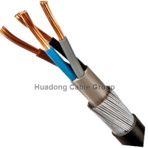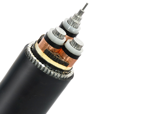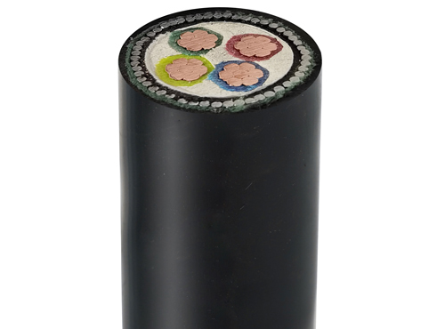
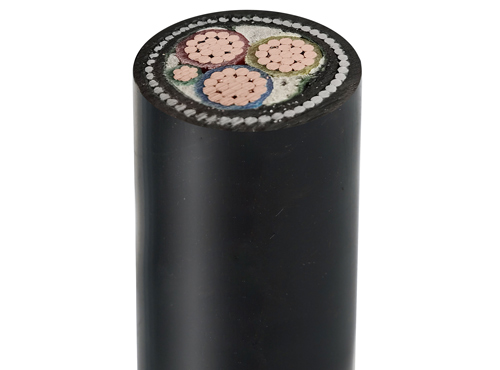
Low Voltage Armoured Power Cable
Available in various sizes, configurations, and voltage ratings, depending on the intended application.
They are designed to meet specific standards and regulations to ensure electrical safety and reliable performance.
Share
Conductor
Class 2 stranded copper conductor
Insulation
XLPE (Cross-Linked Polyethylene)
Bedding
PVC (Polyvinyl Chloride)
Armour
SWA (Steel Wire Armour)/ AWA (Aluminium Wire Armour)
Sheath
PVC (Polyvinyl Chloride)
Low voltage armoured power cable is a type of electrical cable designed for transmitting electricity at low voltages while providing mechanical protection through an armoured layer.
It is commonly used in various applications, including power distribution networks, industrial installations, underground wiring, and outdoor installations where protection against physical damage is required.
The cable consists of multiple conductors, typically made of copper or aluminum, which carry the electrical current.
These conductors are insulated with a layer of material, such as cross-linked polyethylene (XLPE) or polyvinyl chloride (PVC), to prevent electrical leakage and ensure safe transmission.
The number of conductors can vary depending on the specific application and requirements.
IEC 60502-2, BS 7870 or other standard can be customized.
Nominal Conductor Area | No. and Diameter of Wires | Nominal Diameter of Conductor | Maximum Conductor | Nominal Weight per km of |
(mm2) | (no./mm) | (mm) | (0/km) | Conductor (kg/km) |
1 | 7 / 0.43 | 1.29 | 18.1 | 9.2 |
1.5 | 7 / 0.53 | 1.59 | 12.1 | 14 |
2.5 | 7 / 0.67 | 2.01 | 7.41 | 22.4 |
4 | 7 / 0.85 | 2.55 | 4.61 | 36.1 |
6 | 7 / 1.04 | 3.12 | 3.08 | 54 |
10 | 7 / 1.35 | 4.05 | 1.83 | 90.8 |
16 | 7 / 1.70 | 4.69 | 1.15 | 145 |
25 | 7 / 2.14 | 5.9 | 0.727 | 229 |
35 | 7 / 2.52 | 6.95 | 0.524 | 317 |
50 | 19 / 1.78 | 8.4 | 0.387 | 429 |
70 | 19 / 2.14 | 10.1 | 0.268 | 620 |
95 | 19 / 2.52 | 11.9 | 0.193 | 860 |
120 | 37 / 2.03 | 13.5 | 0.153 | 1086 |
150 | 37 / 2.25 | 14.9 | 0.124 | 1334 |
185 | 37 / 2.52 | 16.9 | 0.0991 | 1673 |
240 | 61 / 2.25 | 19.2 | 0.0754 | 2199 |
300 | 61 / 2.52 | 21.5 | 0.0601 | 2759 |
400 | 61 / 2.85 | 24.3 | 0.047 | 3528 |
500 | 61 / 3.20 | 27.3 | 0.0366 | 4448 |
630 | 127 / 2.52 | 32.76 | 0.0283 | 5744 |
800 | 127 / 2.85 | 37.05 | 0.0221 | 7346 |
1000 | 127 / 3.20 | 41.6 | 0.0176 | 9260 |
No. Cores | Conduct or Cross | Cable Cross Section Area (mm²) | Actual Armour Cross Section Area (mm²) | Overall Diameter (mm) | Gland | Cleat Size |
2 | 1.5 | 114.93 | 15 | 12.1 | 20S | 5 |
2 | 2.5 | 145.19 | 17 | 13.6 | 20S | 6 |
2 | 4 | 169.63 | 19 | 14.7 | 20S | 6 |
2 | 6 | 198.46 | 22 | 15.9 | 20 | 7 |
2 | 10 | 254.34 | 26 | 18 | 20 | 8 |
2 | 16 | 326.69 | 42 | 20.4 | 25 | 9 |
2 | 25 | 455.94 | 42 | 24.1 | 25 | 10 |
2 | 35 | 426.17 | 60 | 23.3 | 25 | 10 |
2 | 50 | 522.53 | 68 | 25.8 | 32 | 11 |
2 | 70 | 660.19 | 80 | 29 | 32 | 12 |
2 | 95 | 860.05 | 113 | 33.1 | 40 | 14 |
2 | 120 | 1023.02 | 125 | 36.1 | 40 | 16 |
2 | 150 | 1212.42 | 138 | 39.3 | 40 | 18 |
2 | 185 | 1568.5 | 191 | 44.7 | 50 | 20 |
2 | 240 | 1884.79 | 215 | 49 | 50 | T9 |
2 | 300 | 2246.87 | 235 | 53.5 | 63 | T9 |
2 | 400 | 2732.59 | 265 | 59 | 63 | T10 |
No. Cores | Conduct or Cross Sec- tion Area (mm²) | Cable Cross Section Area (mm²) | Actual Armour Cross Section Area (mm²) | Overall Diameter (mm) |
3 | 1.5 | 124.63 | 16 | 12.6 |
3 | 2.5 | 156.07 | 19 | 14.1 |
3 | 4 | 183.76 | 20 | 15.3 |
3 | 6 | 216.31 | 23 | 16.6 |
3 | 10 | 298.5 | 39 | 19.5 |
3 | 16 | 366.25 | 45 | 21.6 |
3 | 25 | 510.45 | 62 | 25.5 |
3 | 35 | 615.44 | 68 | 28 |
3 | 50 | 637.62 | 78 | 28.5 |
3 | 70 | 813.92 | 90 | 32.2 |
3 | 95 | 1074.67 | 128 | 37 |
3 | 120 | 1281.25 | 141 | 40.4 |
3 | 150 | 1625.15 | 201 | 45.5 |
3 | 185 | 1946.83 | 220 | 49.8 |
3 | 240 | 2383.27 | 250 | 55.1 |
3 | 300 | 2844.87 | 269 | 60.2 |
3 | 400 | 3481.91 | 304 | 66.6 |
No. Cores | Conduct or Cross Section Area (mm²) | Cable Cross Section Area (mm²) | Actual Armour Cross Section Area (mm²) | Overall Diameter (mm) | Gland | Cleat Size |
4 | 1.5 | 143.07 | 17 | 13.5 | 20s | 6 |
4 | 2.5 | 176.63 | 20 | 15 | 20s | 6 |
4 | 4 | 211.13 | 23 | 16.4 | 20 | 7 |
4 | 6 | 274.51 | 36 | 18.7 | 20 | 8 |
4 | 10 | 349.49 | 43 | 21.1 | 25 | 9 |
4 | 16 | 411.66 | 49 | 22.9 | 25 | 11 |
4 | 25 | 597.98 | 70 | 27.6 | 32 | 12 |
4 | 35 | 725.47 | 78 | 30.4 | 32 | 12 |
4 | 50 | 803.84 | 90 | 32 | 32 | 14 |
4 | 70 | 1115.71 | 131 | 37.7 | 40 | 16 |
4 | 95 | 1365.03 | 147 | 41.7 | 50 | 18 |
4 | 120 | 1741.45 | 206 | 47.1 | 50 | 20 |
4 | 150 | 2073.94 | 230 | 51.4 | 50 | TC9 |
4 | 185 | 2514.79 | 255 | 56.6 | 63 | TC10 |
4 | 240 | 3115.75 | 289 | 63 | 63 | TC11 |
4 | 300 | 3715.75 | 319 | 68.8 | 75 | TC12 |
4 | 400 | 4788.19 | 452 | 78.1 | 75 | TC14 |
No. Cores | Conduct or Cross Section Area (mm²) | Stranding mm | Approx weight kg/km | Approx overall diameter | Gland size mm | Single cleat | Nom. Max. DC-resist conductor 20oC ohm/km | Current rating laid direct amp |
5 | 1.5 | 7/0.53 | 395 | 13.72 | 20s | 0.6 | 12.1 | 32 |
5 | 2.5 | 7/0.67 | 497 | 15.46 | 20s | 0.6 | 7.41 | 42 |
5 | 4 | 7/0.85 | 674 | 17.38 | 20 | 0.7 | 4.61 | 55 |
5 | 6 | 7/1.04 | 868 | 19.05 | 20 | 0.8 | 3.08 | 69 |
5 | 10 | 7/1.35 | 1197 | 22.06 | 25 | 0.9 | 1.83 | 92 |
5 | 16 | 7/1.70 | 1780 | 24.14 | 25 | 1.1 | 1.15 | 119 |
5 | 25 | 7/2.14 | 2435 | 28.4 | 32 | 1.2 | 0.727 | 152 |
5 | 35 | 7/2.52 | 2800 | 33 | 40 | 1.4 | 0.524 | 182 |
5 | 50 | 19/1.78 | 3850 | 38 | 40 | 1.6 | 0.387 | 217 |
5 | 70 | 19/2.14 | 5100 | 42.9 | 50s | 1.8 | 0.268 | 266 |
5 | 95 | 19/2.52 | 7700 | 52.1 | 50 | TC9 | 0.193 | 319 |
Manufacturing Process
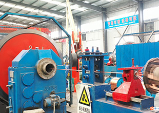
Conductor Stranding

Extruded Insulation

Cabling

Armoured

Extruded Outer Sheath

Packing On Drum

